ROBOTICS CLUB 2024-25
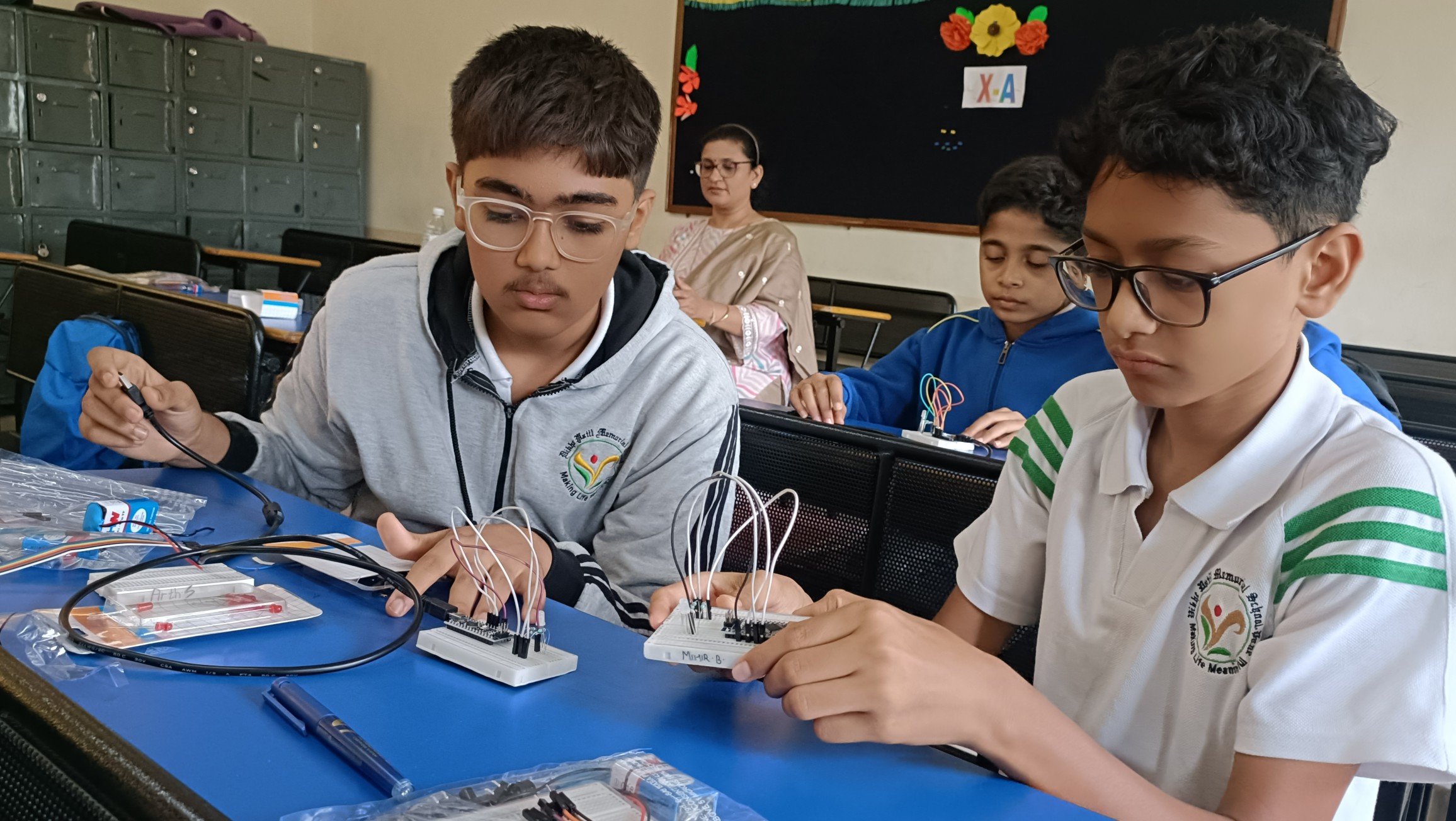
The second activity of the Robotics Club was held on 22 nd June 2024. The club members along with the teachers assembled in Std. X classrooms for the activity. Resource persons from the TinyBots conducted the activities for the students.
The activities of the Robotics Club were held at three levels:
Level 1
Activity 1: Hand Steadiness Tester
Buzz wire is a steady hand game that is well known to many as a table top amusement. It is an activity for children to judge stability of their hand. This is a simple game where they have to get a loop of wire through a maze of other metal wires. If they touch, a buzzer emits a
“buzz”.
Working:
An electric motor converts electric energy into mechanical energy. It works on the principle that when an electric current is passed through a conductor placed normally in a magnetic field, a force acts on the conductor as a result of which the conductor begins to move and
mechanical energy is obtained. Here the copper coil is the current carrying conductor.
Activity 2: Rain Sensor Alarm
A rain sensor or rain switch is a switching device activated by rainfall. There are two main applications for rain sensors. The first is a water conservation device connected to an automatic irrigation system that causes the system to shut down in the event of rainfall.
Working:
There is a small gap between 2 aluminium foil’s semicircles. Drop few drops of water in the gap at center, and the buzzer starts making sound. Aluminium is a good conductor of electricity. When the rain drops fall on the gap at center the circuit is completed through
water and current flows into the buzzer.
Level 2
Activity 1: Mini Grinder/Sander / Polishing Machine
A mini grinder is powered by electricity or compressed air and can be used for a variety of tasks, including removing rust and corrosion, shaping and deburring metal, sanding wood and plastics, and polishing surfaces to a high shine.
Working:
The grinder consists of a motor to which the grinding wheel is attached. When the motor starts the shaft starts spinning which in turns spins the wheel of grinder.
Activity 2: Witricity-Wireless transmission of electricity
Witricity depends upon strong coupled resonance between transmitter and receiver coils. The transmitter emits a non-radioactive magnetic field resonating at MHz frequencies and the receiving unit load resonates in that field.
Working:
The transistor causes the current to change continuously in the coil 2 and hence the magnetic field changes. The change in the magnetic field with respect to time leads to the generation of current in the coil 1.This is known as induction.
Level 3
Activity 1: Arduino programming based colour changing RGB LED
RGB LED means red, blue and green LEDs. RGB LED can emit different colours by mixing the 3 basic colours red, green and blue. So it actually consists of 3 separate LEDs red, green and blue packed in a single case. That’s why it has 4 leads, one lead for each of the 3 colours
and one common cathode or anode depending of the RGB LED type. The code is an Arduino program that simulates a traffic light using RGB Led.
Working:
Variable Declaration: Three variables Red_pin, Green_pin and Blue_pin are declared to store the pin numbers of the rgb Led.
Duration: – An array name light_time is defined to hold the duration for each phase of traffic light separately.
Setup function: – In setup function LED pins are configured to output.
Loop function:- The loop function is where the traffic light logic is implemented. It consists of four loops that iterates three times corresponding to three phase of traffic light cycle red, green and orange. Inside the loop if else condition is used to determine which LED to turn on based on the value of loop variable.
Activity 2: Arduino programming based Piano
Arduino programming based Piano produces a sound of fixed frequency when we press the push buttons. The frequency is predefined for all the keys in the code. It produces a sound of the desired frequency.
Working
This Arduino code creates a simple piano using buttons and a buzzer. It begins by defining pins for the buttons and assigning them to input pins with internal pull-up resistors. Pins for the buzzer are also defined as output pins. In the loop, the code reads the state of each button,
allowing for debounce with a delay of 60 milliseconds. After debounce, if a button is pressed (indicating a low state), the code plays a tone on the buzzer corresponding to the frequency value assigned to that button. The duration of each note is set by the "dr" variable. This process repeats continuously, allowing users to play different notes by pressing the corresponding buttons. Overall, the code enables the creation of a basic piano interface using Arduino, where users can produce different musical notes by pressing buttons. Students actively participated in the activities at various levels. It was a great hands-on learning experience for students.
Report by – Mrs. Anjali Naik
Mrs. Santosh Wadhwa